![]()
The one part that was a bit new to me, was the actual AC dimming itself. So I did a bit of research on the web, and here's a 30-second synopsis of it:
To dim a (resitive) DC element - like an LED, you could to it one of two different ways. The first would be to put a resistor in series with it, limiting the current going to it, as such: This has the major drawback that the resistor will disipate energy as heat, meaning your wasting a lot of power (and generating a lot of heat). Since V=IR and P=VI or P=RII - this means that the greater the current, the greater the power disipated as heat, exponentially. This is not good, if you have a lot of lights.
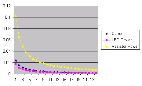
Notice in the graph above, that the resistor always disipates more power than the LED does. This shouldn't come as a surprise, as an LED has a fixed voltage drop of about .7v, whereas the resistor will then have to disipate the remainder, i.e. 5v-.7v=4.3v. This situation gets worse and worse as current increases, because V=IR means that I and R are inversler proportional - so of P=IIR, that means that as R decreses, I will rapidly increase.
The other method is to just blink the LED very fast - full-on, to full-off. This would mean (in the above schematic) that "R" is going from 0 to infinity, back and forth. Idealy, this would be a perfect square-wave, i.e. no in-between resistances. The duty-cycle of your blinking will determine how bright/dim it is. In doing so, in the "full-on" case, you have a resistance of "zero", and therefore no power-disipation (heat) in the resistor, and in the "full-off" case you have no current - therefore again no power-dissipation or heat. Therefore your efficiency is maximized this way. This is the principal behind switching power supplies, and those annoying blinking LED tail-lights in cars thse days.
This is accomplised by means of something called a "zero-crossing detector". This is merely a simple circuit which detects when the AC line is crossing the zero point. What's so special about the zero point?
The largest signifigance is that the Triac - the device used for the actual AC switching - will switch "on" when a signal is present at its "gate", and will remain on until the voltage going through it is zero - i.e. until the zero-crossing. So knowing when the zero-crossing occurs tells us that we have now started the "off" phase of our switching cycle.
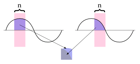
Conversely, the other importiant thing the zero-crossing tells us is that we are at the begninning of a new cycle. i.e. If we were to switch "on" now, we will be at pretty much a 100% duty-cycle. If we wait 8mS (one-half of a 60-Hz cycle) - we will be at a 50% duty cycle.
The importance is that we have to use the zero-crossing as the start-point and the basis for such timings, so that they are consistant and known. i.e. the diagram above shows us that 8mS can give us a different level of brightness, depending on where in the cycle the 8mS is turned-on. The zero-crossing lets us establish that consistant point. However, as the traic will automatically turn-off at the zero-crossing, we have to base all our timings back from there.
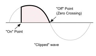
The above diagram shows what a wave looks like when dimmed - it is switched "on" part-way into its AC cycle. Notice that in a normal sine wave, the voltage/current is constantly raised and lowered by smooth, gradual transitions. When we switch it on partway through the cycle, this is not the case. These sharp corners, or abrupt swings in voltage/current are tremendous sources of noise. Such noise can lead to "buzzing" often heard in AC dimmers and transformers, "filliment rattle", which is buzzing in the bulb filiments themselves. This noise can also leak into other devices on your power line. If such noise is an issue, placing a ferrite/choke/inductor in series with the load will slow-down these sharp edges, and eliminate these effects.
By the way - there are a lot of Triacs on the market that have a "zero-crossing circuit" built into them. This circuit is designed to turn the traic on, only when the AC line is at the zero crossing. This eliminates noise, caused by that sharp-ramp-up that can occur when you spontaniously turn "on" in the middle of a nice smooth sine-wave. Be advised that you cannot use such triacs for dimming, as turning on mid-phases is percisely what we need to do to control dimming. (These are used for circuits which mereley switch AC-loads on-and-off).
David Fansler goes into more detail on triacs on his page on dimmers and computer lights